Slice

This modifier either deletes or selects all elements on one side of an infinite cutting plane. Alternatively, the modifier can cut out a slab of a given thickness from the structure.

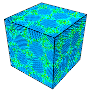
Input

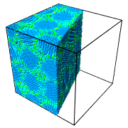
Output (slab width = 0)

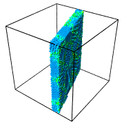
Output (slab width > 0)
Parameters
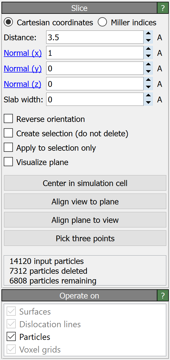
- Cartesian coordinates / Miller indices pro
Selects whether the Distance and Normal parameters are specified in terms of the global Cartesian coordinate system or in reciprocal cell space.
Note: Miller indices are specified in terms of the periodic lattice established by the three simulation cell vectors only, not the physical lattice possibly formed by atoms/particles within the simulation cell, which may be different.
- Distance
The (signed) distance of the cutting plane from the origin measured parallel to the plane normal. In Cartesian mode, the origin is the point (0,0,0) of the global simulation coordinate system and the distance is specified in simulation units of length. In Miller index mode, the plane’s distance is measured from the origin of the simulation cell and specified in terms of the interplanar spacing \(d_{\mathrm{hkl}}\), which depends on the entered Miller indices.
- Normal
The three components of the plane’s normal vector, which defines the orientation of the plane. This vector does not have to be a unit vector. Note that you can click on the blue labels next to each input field to reset the vector to point along the corresponding axis. In Cartesian mode, the normal vector is specified in Cartesian coordinates of the global simulation coordinate system. In Miller index mode, the normal vector must be specified in terms of the reciprocal lattice vectors (inverse simulation cell matrix).
- Slab width
Specifies the width of the slab to cut out from the input structure. If this value is zero (the default), everything on one side of the cutting plane is deleted. If slab width is set to a positive value (measured in simulation units of length), a slice of the given thickness is cut out.
- Reverse orientation
Effectively flips the cutting plane’s orientation. If the slab width parameter is zero, activating this option will remove all elements on the opposite side of the plane. Otherwise this option will let the modifier cut away a slab of the given thickness from the input structure.
- Create selection (do not delete)
This option lets the modifier select elements instead of deleting them.
- Apply to selection only
Restricts the effect of the modifier to the subset of elements that are currently selected.
- Visualize plane
Lets the modifier generate polygonal geometry to visualize the plane in rendered images. Otherwise the plane is only indicated in the interactive viewports of OVITO.
Alignment functions
These functions reposition or align the cutting plane:
Center in simulation cell moves the plane to the center of the simulation cell by shifting it parallel to the plane’s normal vector.
Align view to plane rotates the viewport camera to make it look perpendicular onto the cutting plane.
Align plane to view rotates the plane such that its normal vector becomes parallel with the camera viewing direction of the active viewport.
Pick three points lets you pick three spatial points with the mouse in the viewports. The cutting plane will be repositioned such that it goes through all three points.
Animating the plane
The position of the cutting plane can be animated. Use the A button next to each numerical parameter field to open the corresponding key-frame animation dialog. See the animation section of this manual for more information on this topic.
See also
ovito.modifiers.SliceModifier (Python API)